This page details the building of a portable print display box for lighting and judging prints. This box was build by Ian Findlay during the Christmas holidays of 2011. ©2011 Ian Findlay. All rights reserved. For permission to construct the Light Box or use the design and any other information relating thereto contact Ian Findlay at Dumfries Camera Club.
......................
There are many different ways to build a Print Illuminating Carry Box - PIC Box for short (named by Rod Wheelans whose second choice of name was 'Device Used Mostly For Really Intelligent Entry Scoring' - but the use of the word 'Intelligent' was deemed inappropriate).
This is the second club box I've built and the notes below are by no means the definitive box design for this purpose nor is the joinery. To keep things in perspective - it's an amateur print judging display box built by an amateur joiner. The notes below are neither correct or incorrect but are just the way I built it. You can take out of this some or all of the method if you think it might help.
Brief
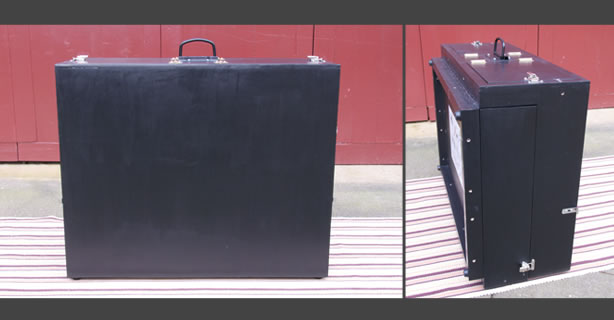
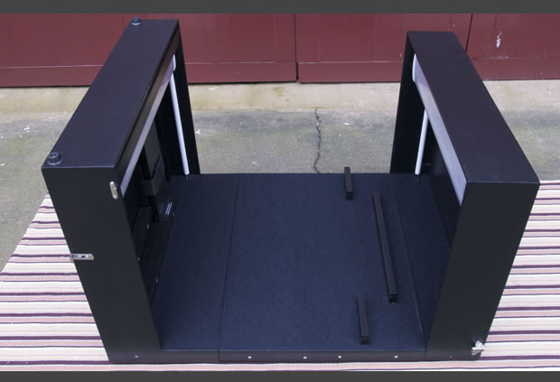
The box had to be big enough to display the standard 40x50cm mounted prints used in amateur competitions. It must contain the lighting, it had to be portable, fit into the boot of a car, not too heavy that you can't carry it and have good even lighting on the print itself. After some lighting deliberation I arrived at this design.
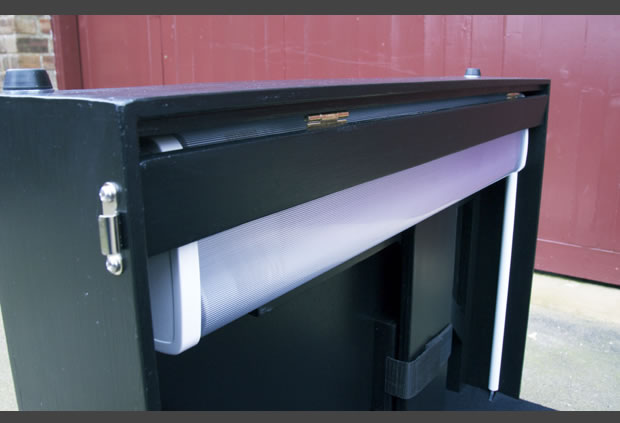
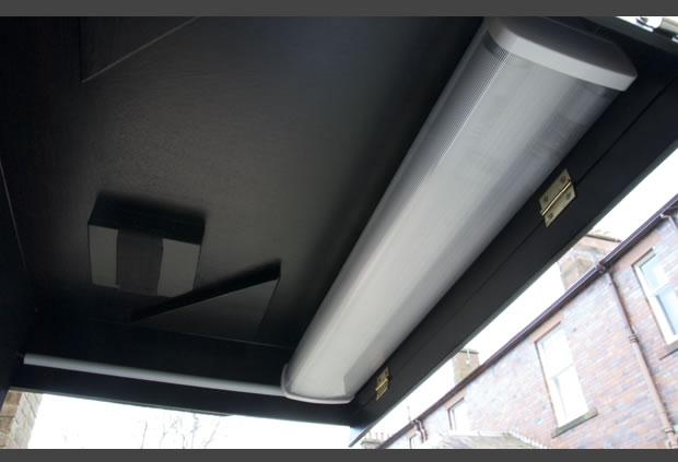
It was important that the lights were a reasonable distance from the print so as not to create 'hot-spots' at the top and bottom of the print where the lights are at their most intense. A distance of about 45 - 50 cm from the face of the back of the box is a good guide. The lighting should be daylight bulbs. I went for two 2ft 18W Twin HF Fluorescent Fitting [update March 2013 - changes bulbs to 13w] (HF - High Frequency keep a consistent brightness for most of their life) with diffusers and 2ft 18W Daylight Triphosphor Fluorescent Tube T8. The four bulbs are almost too bright but the diffusers tone this down and even the light out as well.
What I Used
2x 2ft 18W Twin HF Fluorescent Fitting
4x 2ft 18W Daylight Triphosphor Fluorescent Tube T8 [update March 2013 - changes bulbs to 13w]
2x 2ft Twin Polycarbonate Diffuser
2x Slimplug
1m x 1m Black Self Adhesive Felt
8x 22mm Black Rubber Chair Buffer (feet)
8x 38mm Butt Hinges
4x Magnetic Catches
16x M6 25mm Washers
16x M6 75mm Bolts (Cup Square)
16x M6 Wing Nuts
1x 100mm Chest Handle
4x 45mm Toggle Catch
2x 610mm Piano Hinges
2x mirror supports
Enough 34x34mm planed Softwood
Enough 9mm Ply
Tin of Dark Grey Primer
Tin of Matt Black
Tin of Clear Matt Varnish
Length of sticky backed Cable Trunking
Wood Glue
Wood Filler
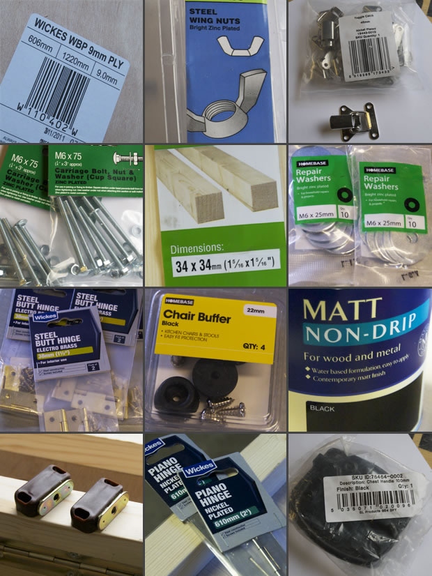
This is the basic list and added to all that were a good selection of nails and screws along the way.
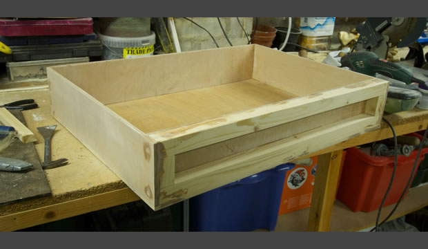
Building the Box
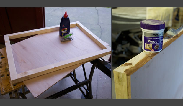
Back Board (A)
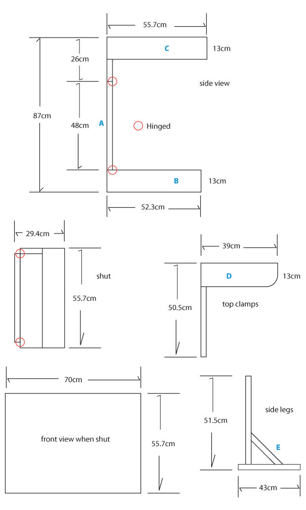
I started with the main back board that the top and bottom light troughs would hinge from. This is a rectangle ply 70cmx48cm attached to a wood frame. I cut the lengths from the 34mm profile wood for the frame 2x 70cm and 2x 48cm. These were notched together (I'll mention this just once - you don't have to do this and use screws or nails if you want but I notched or morticed and glued all the joints to build the box as strong as I could). Cut the 70cm x 48cm ply and nail the ply to the frame using plenty of wood glue. Wipe up any extra glue and clamp it up to dry.
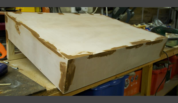
You need to stick rigidly to the sizes for this box to work. It folds in on itself and just a few mm out and it won't work. I remember planing off the top and sides of this to get it the perfect size. Later filler any small gaps or ragged edges on the ply and sand it all smooth. I used a very dark wood filler so I didn't miss any bits when sanding it later - it's getting painted anyway.
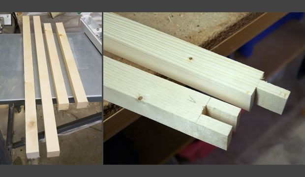
Bottom Light Trough (B)
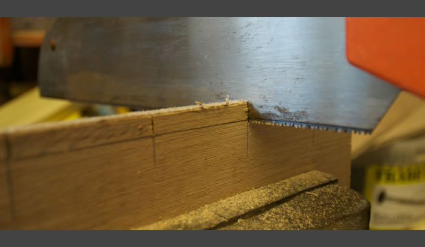
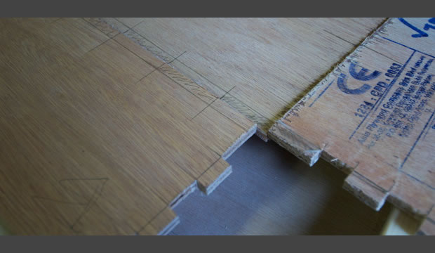
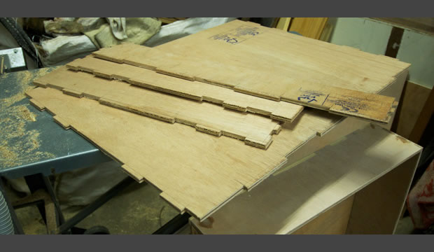
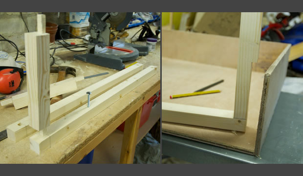
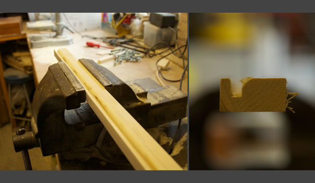
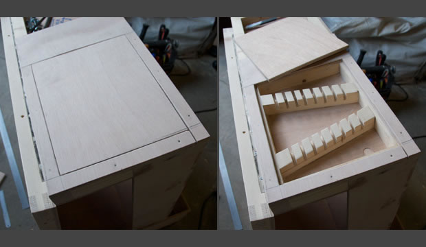
Next I made the bottom light trough. Cut the front edge and the two sides. The front edge is 70cm x 13cm and the 2 sides are 52.3cm x 13cm (OR - and worth double checking at this stage - the length of the sides needs to be the height of the back box plus the depth of the back box ... 48cm plus 34mm frame plus the 9mm ply. So if you're out by a mm then you can match that now). Notch these 3 sides by lying each edge next to the edge it will join and draw lines across each piece of wood. Cut to the depth of 9mm and interweave each like the image below. Just check it all fits together but don't join it together yet. Remember to always keep your pencil as sharp as possible and cut to the left or the right of your pencil marks, so you're cutting on the line taking into account the width of your blade. Chisel out the notches with a very sharp chisel.
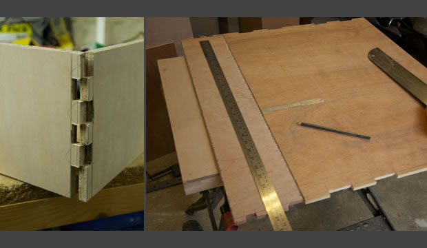
Cut the main base of the trough 52.3cm x 70cm and repeat this notching on all 3 of its sides as well, matching it up with the joining side of the front or edges. Now wood glue every edge and nail together. The end result is so strong you don't need to build a frame to support the trough and this saves loads of weight. Wipe off any extra glue and filler any rags and later sand all the edges smooth.
Next I made the frame for the back of the trough. You need 2x 68.2cm and 2x 12.1cm from the 34mm profile wood. Before you notch and glue together drill 2 holes down through one of the longest edges - I'll go into more detail here: you want 2 slots for bolts that will help to support the box when it's hinged open. I made the mistake of forgetting to do these holes at this stage (although I didn't forget when I did the top trough). Basically, write 'top' on one edge of one of the longest lengths (68.2) and mark it 20cm from the ends and in the middle of the 34mm (17mm). On a bench drill, drill all the way through using a 6mm drill bit (I opened this out later with a 6.5mm drill bit but I used the 6mm first to keep things tight). Back the wood up with some old bits of wood so that the drill doesn't bust its way through and mess up the hole. Notch and glue together with the one marked 'top' facing the top which will be the edge that the hinges go on.
Use the frame to draw round - you need 2 cut shapes of ply - one is a rectangle of the outside and one is a smaller rectangle that will fit inside and put these aside. Slide the frame into the back of the trough with plenty of wood glue, a few nails up from underneath and 4 decent lengthy screws, countersunk and driven into the sides at the tops and bottoms. Deck screws are a good length and I drove them in a few mm off the surface so I could filler over them to keep the box looking good. Get the ply you just cut that fits the full size of the frame and glue and nail that to the frame on the inside face of the trough. Filler any rags and later sand all the edges smooth.
Top Light Trough (C)
Next I made the top light trough. Same as the bottom in method ... cut the front and 2 sides. The front is 70cm x 13cm. The sides are 55.7cm x 13cm (OR - and worth double checking at this stage - the length of the sides needs to be the height of the bottom light trough plus the depth of the back box ... 52.3cm plus 34mm frame plus the 9mm ply. So if you're out by a mm then you can match that now). Notch all the sides as before. Cut the main board 55.7cm x 70cm and notch it as well and glue and nail as before.
Now make the frame out of the 34mm profile wood. 2x 26cm and 2x 70cm for this frame. Drill 2 holes down through one of the longest edges again as you did for the bottom trough frame which you will use to slide bolts through when the box is being assembled. I morticed this frame together making sure my mortice was on the inside edge (because you will need to trim 9mm off from some of the sides and along the bottom so that the frame fits into the trough).
Trim your 9mm making sure the edge with the drill holes is not the edge you're about to trim! Draw round this frame for the inner ply you need and cut this out. Glue and screw the frame to the trough as you did for the bottom trough and glue and nail this last edge in place. Filler any rags and later sand all the edges smooth.
Making the Top Clamps (D)
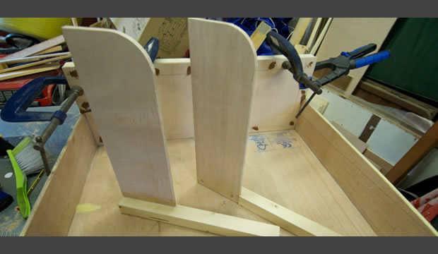
Ok so I messed this bit up and needed to make these parts twice. I stupidly didn't refer to my diagram and measured the wrong side for these clamps. You'll see on the photos that they are too short. D'oh! Anyway you need 2x 50.5cm of the 34mm profile and 2x 39cm x 13cm of the ply. You need to notch the 34mm profile wood 13cm x 9mm deep on one edge at the top so that the ply sits flush. They need to be handed so mark left and right on them (if you're standing at the back of the box then one should have the ply facing forward on the right inside edge to support the top light trough on the left hand side and one on the left inside edge to support the right hand side ... eh, that hardly makes any sense to me and I built it. Just refer to the image below.). Glue and screw these together. Filler any rags and later sand all the edges smooth. I put a curve on them because I thought it looked good and it got rid of some more weight!
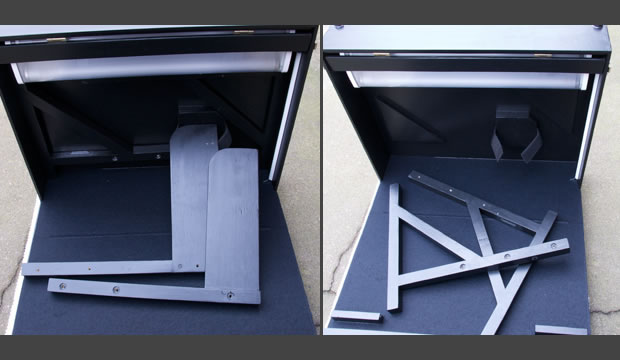
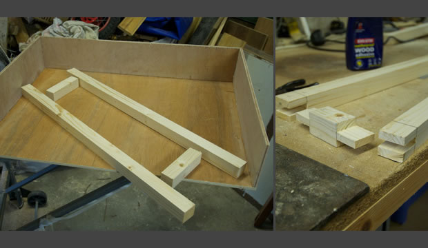
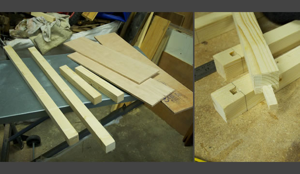
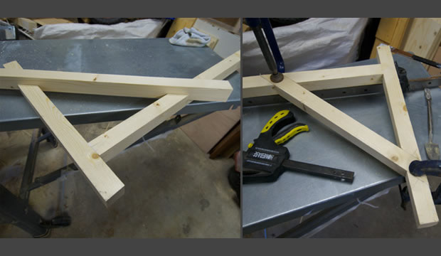
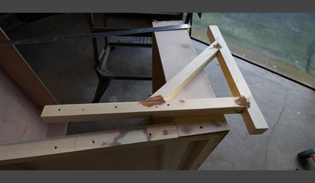
Making the Legs (E)
All made from the 34mm profile wood and build to a size that lets you put them away inside the box when folding shut. Cut 2x 51.5cm and 2x 43cm. Mortice and slot together about 6cm from one end and at a perfect right angle (don't glue yet).
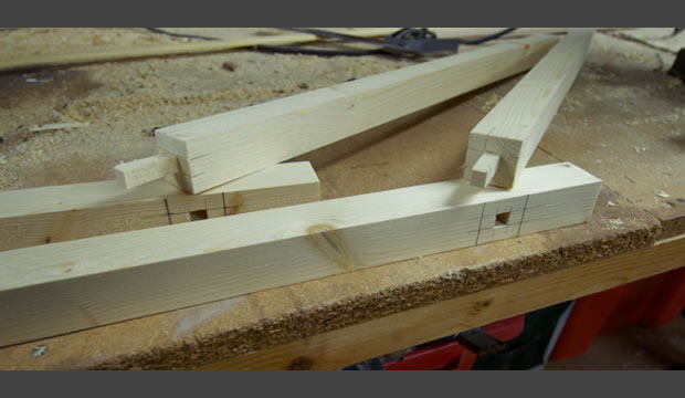
Cut 2 more long pieces of the 34mm that will strengthen this leg at 45 degrees. Lay your long piece starting 6cm from the other end and at a perfect 45 degrees and mark where they overlap. Pull apart again and cut 2 notches 17mm deep on both pieces. Fit back together and slot in your longer length and mark it up to be cut 45 degrees to the correct length, also with a 17mm notch. Glue it all and clamp together. Same for the other leg and then filler any rags and later sand all the edges smooth as usual.
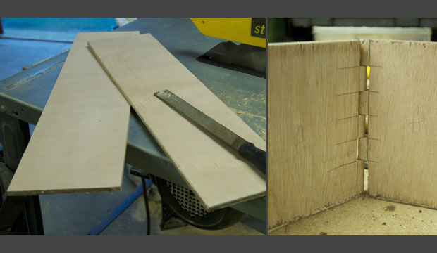
Joining A to B and A to C
This is the difficult part. The exact pivot point of the piano hinge must be in the correct position on the edges that meet. I used a router to do this. Centre the hinge along the length of the bottom light trough and pencil mark the edges of the hinge making sure the pivot point is lined up perfectly with the inside corner.
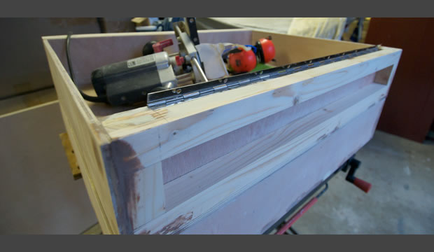
Router the depth you need to make sure that pivot point is in the correct place and you're routering to the edges of your pencil mark. I found this part very stressful and routered the depth I needed a fraction of a mm short at first using the router guide hard against the edge. After 2 passes it was the perfect depth down and distance in. Pilot in 2 screws just to position the hinge for now. Lie part A (the back board) so that the inner corner is tight against the hinge and pencil mark round the hinge on that edge. Your router should be at the perfect depth set from the first cut so now router this edge as well. Pilot just a few screw holes on this edge and screw the hinge into this recess that you've made. I didn't used the supplied screws and used longer ones at about twice the length of the supplied.
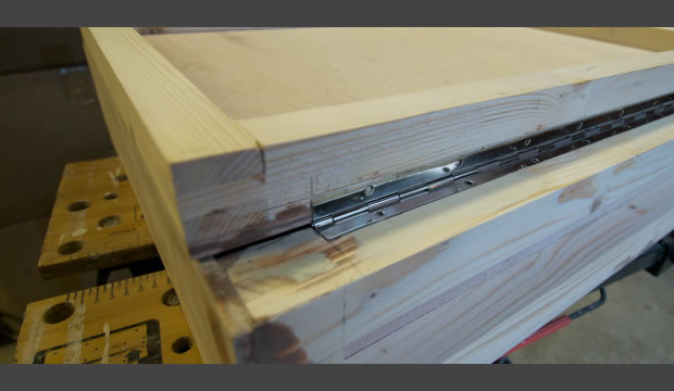
You can test all this now to check that the back board should hinge to make a perfectly flush face with the bottom light trough at a perfect right angle. And when folded it should come to the far edge of the light trough and not fall short (half a mm too long is ok). If all's ok then unscrew it (I only unscrewed it all to get it back in my vice to router the other end of the back board) and router the recess on the back board part A to take the piano hinge for the top light trough C. Now screw on both hinges to join the back board to the bottom light trough A-B. Line it all up with the top light trough part C and pencil mark that hinge recess. Router it and pilot those holes and join it all together. It should open and close perfectly. You might need to sand a few edges here and there so everything is fitting well.
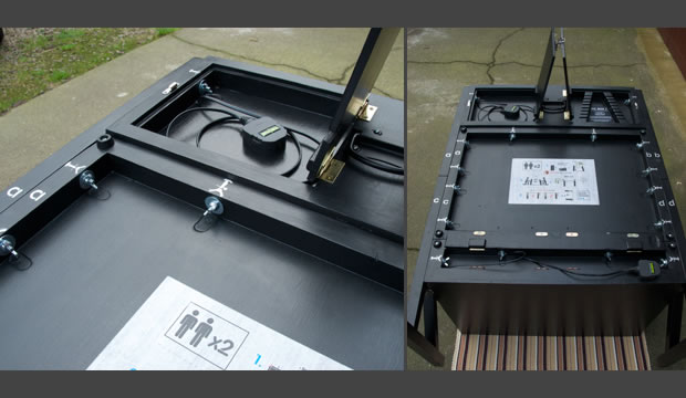
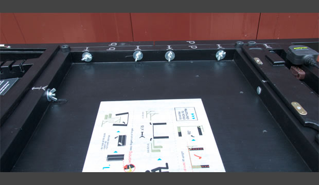
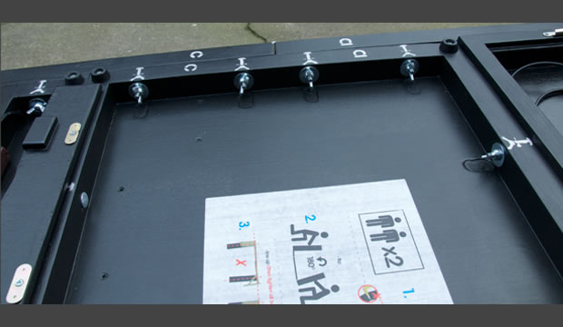
Drilling the bolt holes
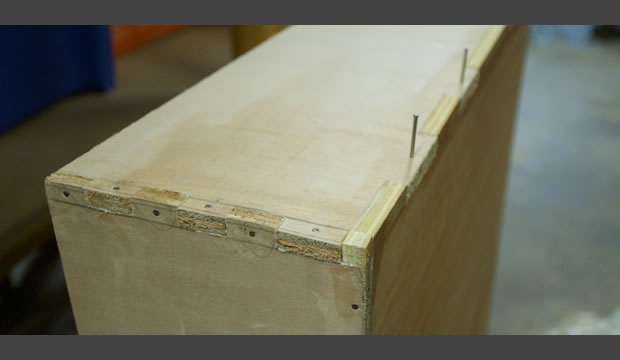
Open the box up lying on its side and clamp the legs or supports in place on the sides. Before drilling make sure that everything is lined up correctly and make sure you're going to be able to fit on wing nuts accessed from the inner edge of the back board. Note: (I forgot to do this sometimes) back this clamped assembly up on the inside edge with some old small cut-offs of wood to stop the drill from bursting through and tearing the wood. You need 3 holes on all 4 side pieces with 2 into the back board and 1 into the top or bottom light trough. You should finish with 6 holes up both sides for bolts and wing nuts. You then need to recess the outside holes on the side pieces so that the bolt heads disappear when assembled. I used a router bit on the bench drill that was the correct diameter for the bolt heads - remember you're only recessing the outside edge of the side parts for the bolts recesses.
You should have 4 more holes next to the hinges on the inside edge of both the top and bottom light troughs that you drilled earlier. With the box opened up - place a bolt in the holes and tap them with a hammer. Close the box to reveal the marks you just made and then very carefully, keeping straight, drill all the way through so the bolt will work when the box is open. You should have 16 bolt holes in total.
Adding the Support Catches
In order for the top clamps to support the weight of the light trough when assembled you need to grab the side clamps as far to the end of the arm as possible. I was going to drill 1 hole in each that passed through the side of the trough and bolt this but then I found 2 old mirror clips which worked perfectly. I positioned them with a small slot on the arm so it all made sense when assembled.
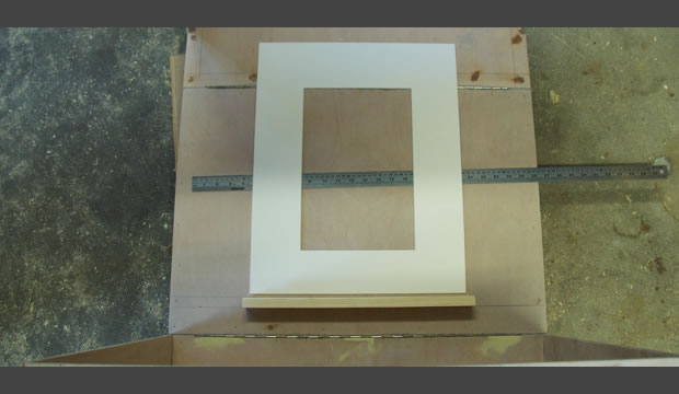
Making the Shelves
I routered out a channel on a long length of wood that had a 35mm x 18mm profile and then cut 3 lengths from this to make my shelves. The channel stops the print from being pushed to the back and then falling over. Lie the box on its back and mark where you want the shelves to be. Drill through the back board then screw from the other side and glue together. Make sure you leave a clearance from the outer edges because the box will fold to take up that space. My inner shelf was 42cm long and positioned 5cm from the bottom hinge and the side shelves were both 13cm long and 13cm from the hinge.
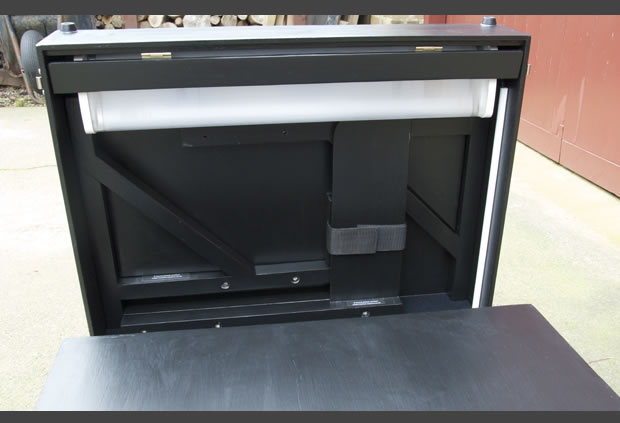
Fitting the Handle Support
Cut two pieces of the 34mm profile wood to the correct length to position inside the frame of the top light trough. Glue and screw into place half way along that edge. Glue a piece of ply over all that. Later, when the box all painted and finished, you can find the fulcrum and position the handle on this plate ensuring the weight is distributed evenly when carried.
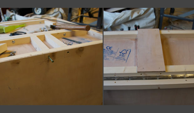
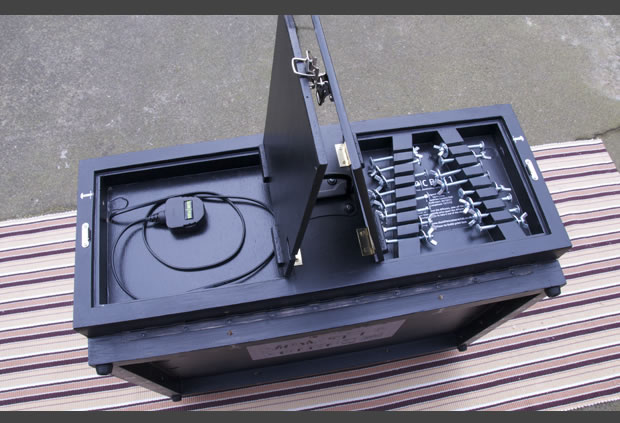
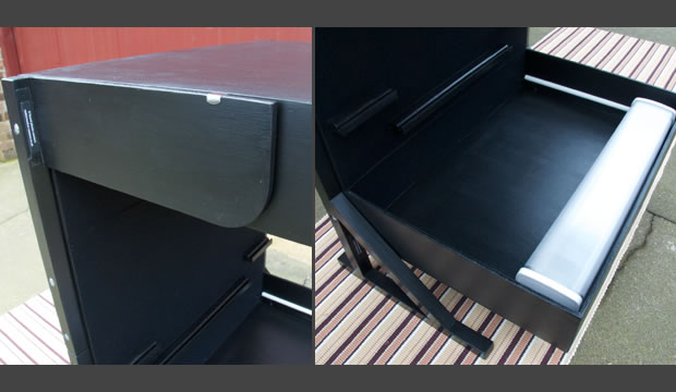
Making the Cubby-holes
Up to you if you want these but I needed somewhere to keep all the parts so nothing got lost in transport. Make and fit some ply round the outside and flush with the edges with a second piece of ply that will make the lid cut to size. Leave a lip of about 5mm on the 3 sides for the lid to settle on. I then made a fancy set of slots to hold all 16 bolts, washers and wing nuts on the right cubby-hole and used the left for the plug and cable for the top lighting. I used the toggle catches on these top 2 lids.
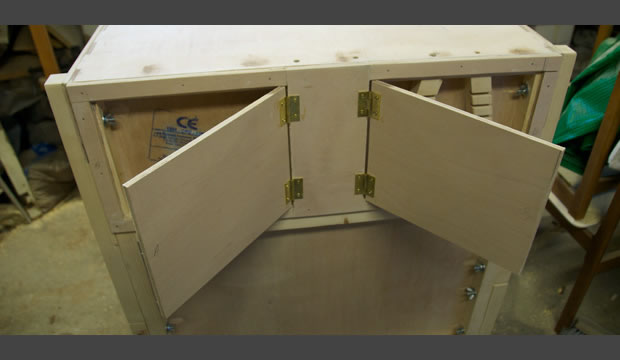
The bottom cubby-hole is made from the ply you cut when you made the bottom frame. This will fit neatly with 2 hinges and 4 magnetic catches and lie flush with the bottom of the box when shut.
Making the Blast Shield
I love the name. Homage to SW. This stops the top light from blasting your eyes which might happen if the box is placed quite high up and the judges are sitting quite close. Make 2 lengths of ply about 4.5cm x 68cm and attach one to the inside front bottom edge of the top light trough. Butt the other next to it and mark where your hinges need to be so it folds neatly out the way. Confused? then check out the finished photos.
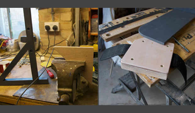
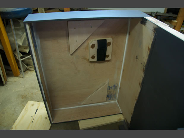
Making the Parts Holders
You need to make 2 triangles that fit the inside of the legs and another piece of square ply that can hold some velcro. You could make this anyway you like but I positioned the 2 triangles so that the legs (parts D) would be held in place and then I made a velcro holder that grabs the side clamps (parts E) which in turn holds everything in place. The triangles are 2 bits of ply thick. For the square piece I routered a channel the width of the velcro on the face of the ply which was screwed onto another shaped piece of wood (you might notice the mistake I made here in the pictures below and needed to make this again as I had the velcro going the wrong way). The velcro holder needs to be 34mm deep so it can clear the legs to grab the clamps (see finished images as well).
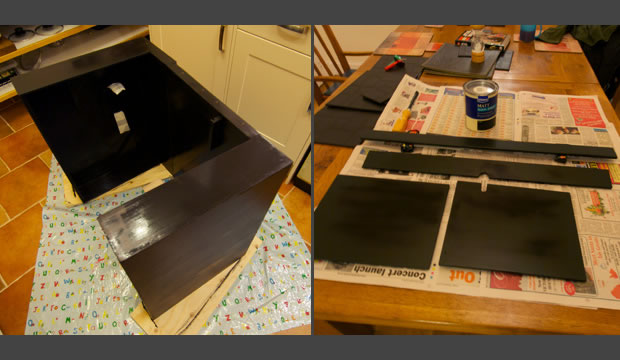
Painting the Box
I've painted 3 club boxes now and never been all that happy with any of them. You can get some really good matt blacks but you just need to look at them and they mark and after a bit of use they look really tatty. I've used a good craft spray paint before but it's very costly. Firstly, I dismantled everything I'd done - but not the main piano hinged joins of A,B&C. I used a dark grey primer on everything and then sanded it all down gently. I then used 2 coats of matt black and finally a thin coat of clear matt varnish. The varnish added a small amount of unwanted sheen but not much and it means the box can be handled without marking it easily. Once dry, then assemble it all back together again.
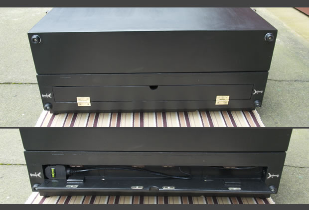
Adding the Feet
You need 8 feet - 4 in each corner of the back board and 4 in each corner of the bottom when folded shut.
Adding the Toggle Catches
Making sure you miss where the legs are positioned, attach the 2 toggle catches where the top light trough (part C) meets the bottom light trough (part B) when folded. Put the hook on part C so the toggled other part dosn't dangle in view when the box is opened and in use.
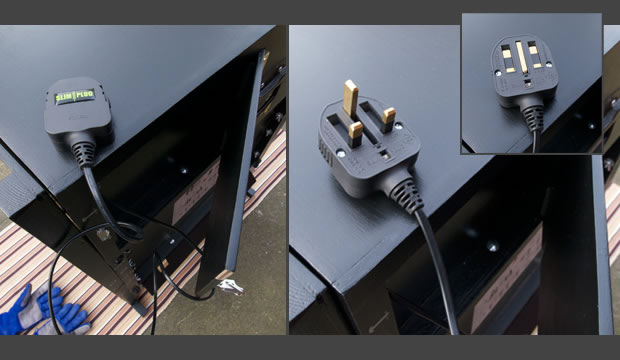
Adding the Lights
Place the light so you can get the diffusers off (make sure you've got at least 40cm of space left over in the top light trough to accommodate parts D) and screw them in place. Run the cable through their 2 small holes that you need to drill inside each of the cubby-holes that will house your extra cable and plugs. Wire them up. Fix the cable out the way inside the trough as you see fit (I used a length of sticky back cable tidy). The images show the Slimplug which folds flat when you hold some little buttons and give them a wiggle but they are not earthed and so no good for any metal boxed strip light. Drill 3 small holes inside the cubby-holes to accommodate a normal plug when the box is folded shut. Drill them as tight to the corners of the box as possible so they'll never be seen when in use.
Adding the Felt
I used self adhesive felt to cover all of the back of the box when open. I needed to make sure the silver piano hinges weren't seen when judging and they constantly rubbed off the paint I had applied when opening and closing. I gave that face of the box a final sand down to take off any small bumps and cleaned it. I ran a small sliver of vaseline along the hinges so that the adhesive wouldn't stick to them. The felt worked a treat although it was very fiddly to apply. I made a template from old wall paper and cut the felt shape out with a scalpel on a cutting mat. I then carefully applied it to the box. Good luck with that.
...........
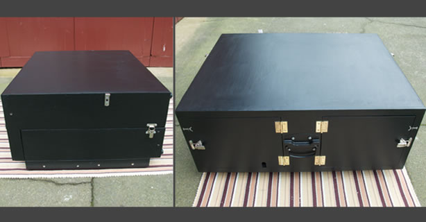
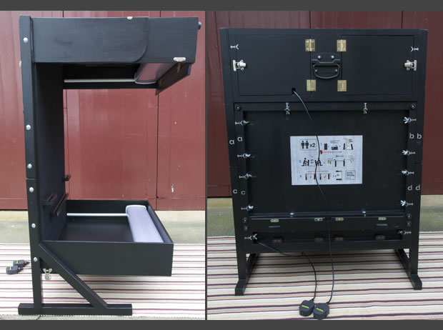
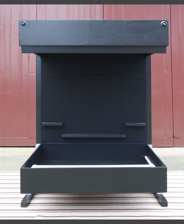
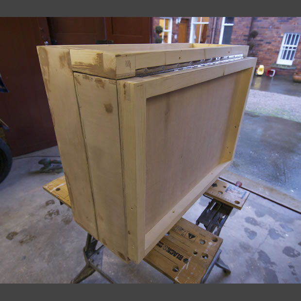
There are lots of other small things that needed to be done, like some paint retouching on bashes and scrapes, choosing all the correct size of screws so that they didn't pop through the ply or backing the ply up here and there so I could use longer screws. I needed a few channels so the cables could fit through the cubby-hole lids when shut. Routered a few mm out of the bottom cubby-hole so the plug fitted in. Routered some clearing space for all the wing nuts to turn freely. I also added instructions stuck on the back and spray painted some markers so it could be assembled easily by 'intelligent' people who can read and follow instructions carefully. As I mentioned at the start this is just how I built this box and here are a few more images of the finished PIC Box.
Ian